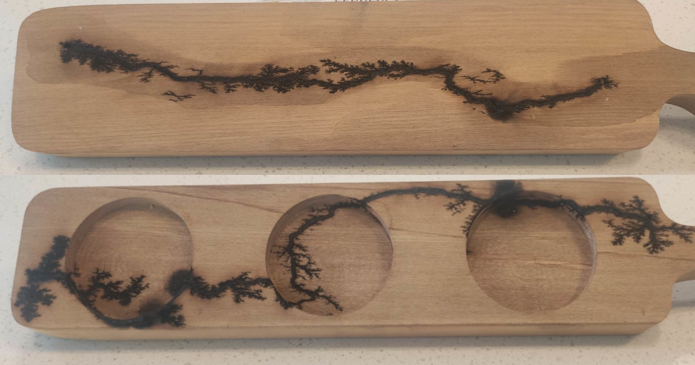
This is a proof of concept project for the development of my plasma speaker controller. It started off as us looking for a way to produce Lichtenberg figures in wood by using a decommisioned/faulty 45kV laser power supply.
After fiddling around with the control inputs on the power supply, we were able to create arcs using a basic voltage divider to as input for our power supply. From there, nails were inserted into wooden boards along with an application of an electrolytic solution on the board. From there, we used our 45kV DC power supply to create our Lichtenberg figures.

Overall, the results were good. We managed to get some nice looking fractal imagery on the wooden board.
With the success of our wood burning experiments I was inspired to use the 45kV DC Power Supply as a plasma speaker. The basic concept was to use my smart phone’s audio jack to output an audio signal into a control circuit which modifies the signal so that the power supply can accept it and produce sound by arcing across two objects.
As far as the control circuit was concerned, I wanted to change the audio input from an $\pm$1V AC to either a 0-5V PWM signal or a 0V-5V AC signal.
I decided to construct both so that I could perform a comparison and see which system performs better.
To reduce the risk of damaging the power supply by over or undervolting the input control pin on it, I decided to only use power rails for Ground and VCC (5V) supplied by the unit.
With that in mind, my control systems would make use of an LM324 quad op-amp powered by a single supply.

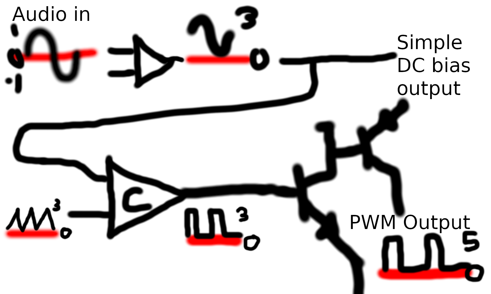
Here I’ve poorly drawn a basic block diagram of my control circuitry (should’ve just used paper) . First we take the audio output and use the LM324 to generate a DC offset for it. From there, we can either feed that signal straight into the unit or further process the signal into a PWM format.
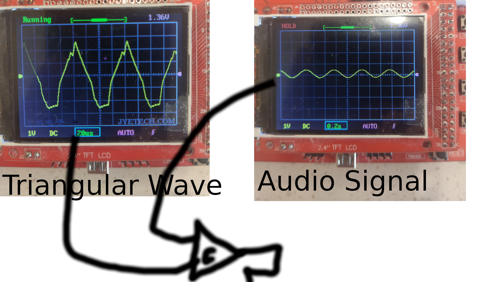
To convert it to a PWM signal, we simply use a digital comparator circuit and compare a triangular wave to the signal.
The triangular wave was created using the two opamps in the LM324. After the PWM signal is generated, we feed it into a high-side transistor switch to bring it up to 5 volts (the unit’s maximum rated control input).

In the video above, you can clearly see how with a 1-4hz input compared to the triangular wave, an oscillating PWM signal of the same frequency is generated. Here's a demonstration video so you can see how it performed.
Overall, I am happy with the performance of the plasma speaker. In the future if I come back to work on a similar project, I will use a 555 timer to generate the triangular wave - that should create a more triangular triangle. There is notable discontinuation in the resulting PWM because of that. I would also like to reduce the time it takes for the output PWM signal to go from 5V to 0V.
I would also like to experiment with using different electrodes to try and create a more stable arc in an attempt to reduce the noise caused by the arc flickering. Ideally I’ll build a unit with different mode selection to easily swap between speaker mode and fractal burning mode.